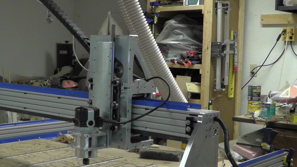
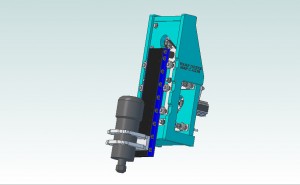
Warp Drive Project Story.
MY CNC JOURNEY 
IN THE BEGINNING
I have been building CNC Router tables since about 2005. I wanted a CNC Router table to make it easier for me to make model airplane kits and custom parts. Commercial CNC machine were very expensive (and still are) and were out of my reach. So I decided I would try and build my own after I saw a set of plans on the internet. My first efforts were made from MDF, Gas pipe and roller skate bearings. I soon realized that my MDF machine was finicky and too small. So I began design work on a larger machine. About the time I got the drawings finished, Joe Cantrill came out with his plans for an even larger machine. I dropped my design and began building his tested design instead.
I completed construction of my second machine in 2009. It was called a Joescnc 4×4 Hybrid. It consisted of MDF carriages, 8020 aluminum extrusions and a Unistrut base. Over the years I have made several changes to the base machine and each has been a step forward.
RACK & PINION
Within a year of completing the machine I decided I wanted to upgrade some components to make the machine faster. The limiting factor with the machine was that it used leadscrew to drive the carriages back and forth. To go faster you had to spin the leadscrews faster and that caused them to deform. If you used a thicker leadscrew you needed a bigger motor. If you needed bigger motors you also need a bigger power supply. Fortunately CNCrouter parts introduced a rack & pinion drive system to eliminate this problem. I was among the first people to use these drive systems to modify the Joescnc router. First I eliminated the ACME leasdcrews and added Rack & Pinion drives from CNCRouterparts. Then I began experimenting with making the Z axis faster by changing the leadscrew to a faster thread pitch.
The modifications I made to the machine were good ones. The machine was faster and had many fewer problems. However the weather in my environment was causing my machine fits. I live in the cold cold North. Temperatures drop below freezing quite frequently. With those low temps, the leadscrew couplers on the Z axis becomes unreliable. I tried to solve the problem by switching to a metal CNCROUTERPARTS Zero Backlash Helical Shaft Coupler. This reduced the problem but still wasn’t the answer I wanted. I looked closer at the problem and discovered that the flange bearing we used were binding in cold weather. I think it was because of the grease lubrication changing viscosity but I am not certain. I just knew they had to go.
OFF WITH THEIR HEADS
I began thinking about making a machine that had R&P on all axis. having a Rack & Pinion Z axis would eliminate the couplers, leadscrews and the flange bearings.I had never heard of a R&P Z axis so I thought I was making a unique system. After a bunch of research I find that there are several systems already out there so I felt confident I could build my own. My old leadscrew Z axis worked reliably at 75 IPM. I realize many can make theirs work at higher speeds but few were doing so. I posted questions to users about how fast their Z was and the fastest I recall was about 150 IPM. I decided to remove every part of my machine above the base and try to improve on them.
WARP DRIVE PROJECT
In 2010 I redesigned every major part of my CNC machine and began test cutting with it for several months. It worked really well. I spent over a year working on this project and built 3 different versions before it was bullet proof. I called the resulting machine the Warp Drive Project. I began design of the carriages in November of 2010 and built the first set of parts in March 2011. The first sets didn’t work as well expected so I won’t go into the details but it was promising and proved the concept was worth pursuing. I went back to the drawing board and  built a new set of parts in June of 2011. This set worked exactly as I hoped. Right after i got the machine working I got sick for about two weeks and then did some traveling following that. Therefore it wasn’t till August that I got to use the machine regularly.
My immediate goal was to make a new X-Z carriage that would replace the leadscrew carriages used on the Joescnc Hybrid. I wanted it to be easy to make and use as few parts as possible. I also wanted it to reuse parts we already had as much as possible, to use construction methods we were comfortable with and not require special tools.
After months of the machine working well, I began working on the finished drawing. I took many videos during the construction and design process. I have posted some of them to youtube. Here are the Design Goals and criteria I set out to achieve (and did) in the Warp Drive Project.
DESIGN GOALS:
1. Replace Leadscrew with R&P
2. Use as few parts as possible.
3. 300 IPM travel on Z.
4. Eliminate problems with cold weather
5. No wobble in the axis (6 bearings).
6. Fit conventional Joescnc machines without major modifications.
7. Increase Z axis travel.
8. Be able to easily change to aluminum construction later.
9. Lends itself to laser cut steel later.
10. No missed steps.
11 Eliminate Flange bearings.
Once I completed the Warp Drive carriages in MDF I shared pictures of the machine on several forums I belong to. I got quite a few questions from interested builders. The most frequent question I got was doesn’t your Z carriage need to be counterbalanced to  prevent the router from dropping when power is turned off? The fact is I haven’t needed any counterbalance. I tested the system up to 14 pounds (all the weight I had) and no counter balance was needed. With the gearing and the natural friction between the components, there is not enough force from gravity to cause the Z plate to drop. If an external force is applied you can move the plate though.
WHY BOTHER?
So why would I spend a year designing a new X-Z carriage when the existing ones worked in most situations? The short answer is because I can. The long answer is because I am a maker and I like to make thing that exactly fit my needs. I wanted to be able to reliably cut 3D CNC projects faster than before. I wanted to know that when I fired up the Router in the middle of winter, it would work just like it is supposed to. I have a need to push the boundaries when I make something. If fast is good, faster is better. Lastly I like to share and teach others how to do what I am doing.
My mom used to have a saying “Each One, teach one.” My mom was constantly teaching me life lessons and encouraged me to try new things. Maybe that is why I bother creating a machine that few people will build. I am hoping to find that one person who “GETS IT”. I want to teach them the way to make CNC avialable and easier without having to mortgage the house to play along. Then, If I do it right they will teach someone else and soon we will have a community of makers who “GET IT.”
To see how this actually worked out for me, check out part two of this story.
NEXT TIME
In Part two of the story I will tell you about the interesting new friends I met as a result of building the Warp Drive Project. I will also talk about how I am keeping my promise to my mom.
If you would like to be notified when I post the second part of the story, why not sign up for my free newsletter.


Pingback:Suggest a CNC Router for around $5000.00 - Page 3 - Router Forums
Pingback:new to CNC world - Router Forums